NetWorker Daily Status Report

Unhappy with the overly verbose native EMC NetWorker savegroup completion reporting and the limited formatting options available in the native html output provided by gstclreport I decided to quickly create a powershell script to produce a a better looking daily status email.  Below is ver 0.1 of the script.

Note:  In the powershell source included below all the variables are in the source for simplicity purposes. In my implementation a large number of the defined variables are used across a wider library of powershell scripts so the variables are actually contained in a separate variable file which I dot source to set the variables in the global scope.

https://gist.github.com/rbocchinfuso/06ad8a9aef58598f3660

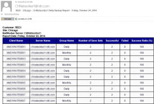
The script delivers via email a message which contains a formatted html report in the body of the email as well as a csv attachment containing the raw data.  The following is a sample email:nwreport1


EMC Forum 2014 New York – It’s all about the cloud and SDW!!

This years EMC Forum 2014 New York is approaching quickly, October 8th is just around the corner and I am really excited!!!

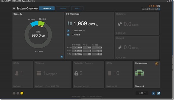
Over the years we (FusionStorm NYC) have typically prepped a demo for EMC Forum and rolled a 20U travel rack complete with networking, servers, storage arrays, and whatever else we needed for the demo to EMC Forum.  In the past we’ve done topics like WAN Optimization, VMware SRM, VMware vCOps, and last year XtremSW.  As a techie it’s always been cool to show the flashing lights, how things are cabled, etc… but this year it’s all about the cloud, commodity compute and and SDW (Software Defined Whatever) and elasticity which is why there will be no 20U travel rack, nothing more than a laptop and an ethernet cable that will connect to a ScaleIO 1.3 AWS (Amazon Web Services) implementation.  The base configuration that I have built in AWS specifically for EMC Forum looks like this:

  • 10 x SDS (ScaleIO Data Server) Nodes in AWS (SLES 11.3)
    • Each node has 1 x 100 GB EBS SSD attached
  • 1 x SDC (ScaleIO Data Client) Node in AWS (Windows 2008 R2)
    • Using IOmeter and vdbench on SDC to generate workload
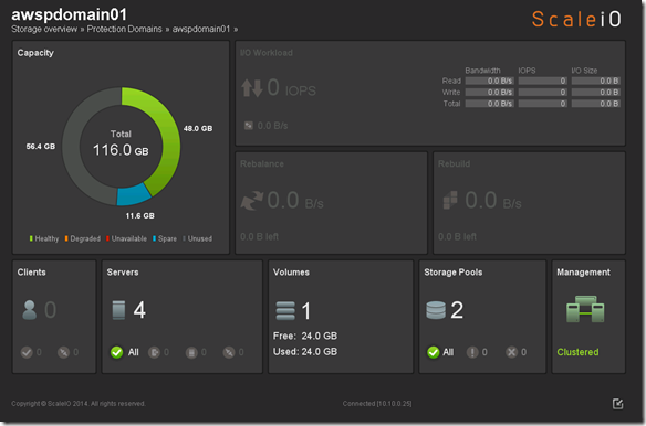
  • Single Protection Domain:  awspdomain01
  • Single Pool:  awspool01
  • 40GB awsvol01 volume mapped to Windows SDC

image

Terminology:

  • Meta Data Manager (MDM) – Configures and monitors the ScaleIO system. The MDM can be configured in a redundant Cluster Mode with three members on three servers, or in a Single Mode on a single server.
  • ScaleIO Data Server (SDS) – Manages the capacity of a single server and acts as a backend for data access. The SDS is installed on all servers that contribute storage devices to the ScaleIO system. These devices are accessed through the SDS.
  • ScaleIO Data Client (SDC) – A lightweight device driver that exposes ScaleIO volumes as block devices to the application residing on the same server on which the SDC is installed.

New Features in ScaleIO v1.30:
ScaleIO v1.30 introduces several new features, listed below. In addition, it includes internal enhancements that increase the performance, capacity usage, stability, and other storage aspects.

Thin provisioning:
In v1.30, you can create volumes with thin provisioning. In addition to the on-demand nature of thin provisioning, this also yields much quicker setup and startup times.
Fault Sets: You can define a Fault Set, a group of ScaleIO Data Servers (SDSs) that are likely to go down together (For example if they are powered in the same rack), thus ensuring that ScaleIO mirroring will take place outside of this fault set.
Enhanced RAM read cache: This feature enables read caching using the SDS server RAM.
Installation, deployment, and configuration automation:  Installation, deployment, and configuration has been automated and streamlined for both physical and virtual environments. The install.py installation from previous versions is no longer supported.
This is a significant improvement that dramatically improves the installation and operational management.

image

image

image

VMware management enhancement: A VMware, web-based plug-in communicates with the Metadata Manager (MDM) and the vSphere server to enable deployment and configuration directly from within the VMware environment.

GUI enhancement: The GUI has been enhanced dramatically. In addition to monitoring, you can use the GUI to configure the backend storage elements of ScaleIO.

GUI enhancements are big!!

clip_image002

clip_image002[5]

Active Management (huge enhancement over the v1.2 GUI):

imageimage

Smile Of course you can continue to use the CLI Smile:

  • Add Protection Domain and Pool:
    • scli –mdm_ip 172.31.43.177 –add_protection_domain –protection_domain_name awspdomain01
    • scli –mdm_ip 172.31.43.177 –add_storage_pool –protection_domain_name awspdomain01 –storage_pool_name awspool01
  • Add SDS Nodes:
    • scli –mdm_ip 172.31.43.178 –add_sds –sds_ip 172.31.43.177 –protection_domain_name awspdomain01 –device_path /dev/xvdf –storage_pool_name awspool01 –sds_name aws177sds
    • scli –mdm_ip 172.31.43.178 –add_sds –sds_ip 172.31.43.178 –protection_domain_name awspdomain01 –device_path /dev/xvdf –storage_pool_name awspool01 –sds_name aws178sds
    • scli –mdm_ip 172.31.43.178 –add_sds –sds_ip 172.31.43.179 –protection_domain_name awspdomain01 –device_path /dev/xvdf –storage_pool_name awspool01 –sds_name aws179sds
    • scli –mdm_ip 172.31.43.178 –add_sds –sds_ip 172.31.43.180 –protection_domain_name awspdomain01 –device_path /dev/xvdf –storage_pool_name awspool01 –sds_name aws180sds
    • scli –mdm_ip 172.31.43.178 –add_sds –sds_ip 172.31.43.181 –protection_domain_name awspdomain01 –device_path /dev/xvdf –storage_pool_name awspool01 –sds_name aws181sds
    • scli –mdm_ip 172.31.43.178 –add_sds –sds_ip 172.31.43.182 –protection_domain_name awspdomain01 –device_path /dev/xvdf –storage_pool_name awspool01 –sds_name aws182sds
    • scli –mdm_ip 172.31.43.178 –add_sds –sds_ip 172.31.43.183 –protection_domain_name awspdomain01 –device_path /dev/xvdf –storage_pool_name awspool01 –sds_name aws183sds
    • scli –mdm_ip 172.31.43.178 –add_sds –sds_ip 172.31.43.184 –protection_domain_name awspdomain01 –device_path /dev/xvdf –storage_pool_name awspool01 –sds_name aws184sds
    • scli –mdm_ip 172.31.43.178 –add_sds –sds_ip 172.31.43.185 –protection_domain_name awspdomain01 –device_path /dev/xvdf –storage_pool_name awspool01 –sds_name aws185sds
    • scli –mdm_ip 172.31.43.178 –add_sds –sds_ip 172.31.43.186 –protection_domain_name awspdomain01 –device_path /dev/xvdf –storage_pool_name awspool01 –sds_name aws186sds
  • Add Volume:
    • scli –mdm_ip 172.31.43.178 –add_volume –protection_domain_name awspdomain01 –storage_pool_name awspool01 –size 40 –volume_name awsvol01
  • Add SDC:
    • Add Windows SDC (would look different on Linux / Unix):
      • C:\Program Files\EMC\ScaleIO\sdc\bin>drv_cfg.exe –add_mdm –ip 172.31.43.177,172.31.43.178
        Calling kernel module to connect to MDM (172.31.43.177,172.31.43.178)
      • ip-172-31-43-178:~ # scli –query_all_sdc
        Query all SDC returned 1 SDC nodes.
        SDC ID: dea8a08300000000 Name: N/A IP: 172.31.43.7 State: Connected GUID: 363770AA-F7A2-0845-8473-158968C20EEF
        Read bandwidth:  0 IOPS 0 Bytes per-second
        Write bandwidth:  0 IOPS 0 Bytes per-second
  • Map Volume to SDC:
    • scli –mdm_ip 172.31.43.178 –map_volume_to_sdc –volume_name awsvol01 –sdc_ip 172.31.43.7

REST API:  A  Representational  State  Transfer  (REST)  API can be used to expose monitoring and provisioning via the REST interface.
OpenStack support:  ScaleIO includes a Cinder driver that interfaces with OpenStack, and presents volumes to OpenStack as block devices which are available for block storage. It also  includes an OpenStack Nova driver, for handling compute and instance volume-related operations.
Planned shutdown of a Protection Domain:  You can simply and effectively shut down an entire Protection Domain, thus preventing an unnecessary rebuild/rebalance operation.
Role-based access control: A role-based access control mechanism has been introduced.
Operationally Planned shutdown of a Protection Domain is a big enhancement!!

IP roles: For each IP address associated with an SDS, you can define the communication role that the IP address will have: Internal—between SDSs and MDMs; External—between ScaleIO Data Clients (SDCs) and SDSs; or both. This allows you to define virtual subnets.
MDM— IP address configuring: You can assign up to eight IP addresses to primary, secondary, and tie-breaker MDM servers, thus enhancing MDM communication redundancy. In addition, you can configure a specific IP address that the MDM will use to communicate with the management clients. This enables you to configure a separate management network so you can run the GUI on an external system.

Note:  The above new features where taken from the Global Services Product Support Bulletin ScaleIO Software 1.30 (Access to this document likely requires a support.emc.com login).  I have played with most of the new features but not all of them, IMO v1.3 provides a major a leap forward in usability.

While big iron (traditional storage arrays) probably are not going away very soon the cool factor just doesn’t come close to SDW (Software Defined Whatever) so stop by the FusionStorm booth at EMC Forum and let’s really dig into some very cool stuff.

If you are really interesting in digging into to ScaleIO one-on-one please email me (rbocchinfuso@fusionstorm.com) or tweet me @rbocchinfuso and we can setup a time where we can focus, maybe a little more than will be possible at EMC Forum.

Looking forward to seeing at the FusionStorm booth at EMC Forum 2014 New York on October 8th.  If you haven’t registered for EMC Forum you should register now, Forum is only 12 days away.

ScaleIO – Chapter III: Scale out for what?

ScaleIO – Chapter III:  Scale out for what?  Answer:  Capacity, performance, because it’s cool and because of AWS I can.

So at this point I decided I wanted to deploy 100+ SDS nodes in AWS, just because I can.

Note:  I attempted to be as detailed as possible with this post but of course there are some details that I intentionally excluded because I deemed them too detailed and there may be some things I just missed.

The first thing I did was create an AMI image using one of the fully configured SDS nodes, figured this would be the easiest way to deploy 100+ nodes.  Being new to AWS I didn’t realize the node I was imaging was going to take the node offline (actually reboot the node, I noticed later that there is a check box that allows you you chose if you want to reboot the instance or not).  There is always a silver lining especially when the environment is disposable and easily reconstructed.

When i saw my PuTTY session disconnect I flipped over to the window and sure enough there it was:Image(33)

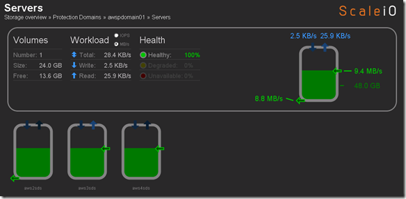
Flipped to the ScaleIO console, pretty cool (yes I am easily amused):Image(34)
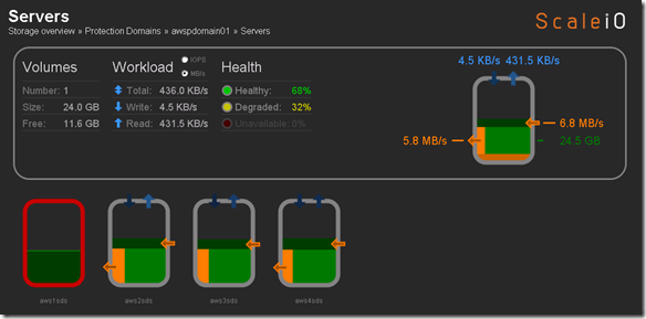
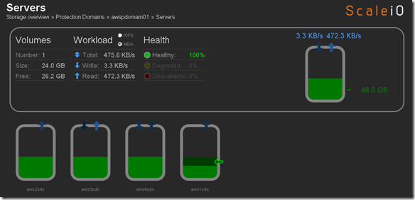
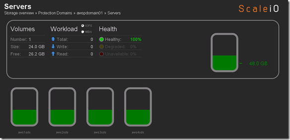
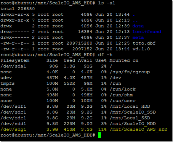
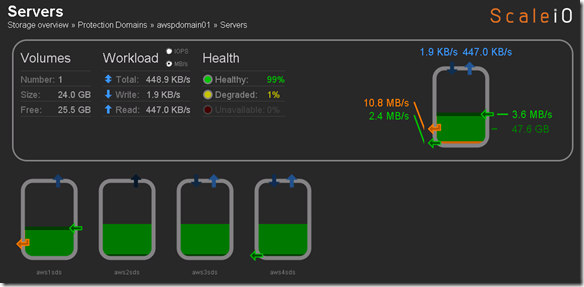
aws1sds node down and system running in degraded mode.  Flipped to the Linux host I have been using for testing just to see if the volume was accessible and data was intact (appears to be so although it’s not like I did some exhaustive testing here):Image(35)
Flipped back tot he ScaleIO console just to see the state and aws1sds was back online and protection domain awspdomain01 was re-balancing:Image(36)
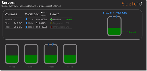
Protection Domain awspdomain01 done rebalancing and system returned to 100% healthy state:Image(37)
So now that my AMI image is created I am going to deploy a new instance and see how it looks, make sure everything is as it should be before deploying 100+ nodes.

Image(38)

Selected instance, everything looked good just had to add to the appropriate Security Group.

Named this instance ScaleIO_AWS5 and I am going to add to existing awspdomain01 as a test.  When I do the 100 node deployment i am going to create a new Protection Domain, just to keep things orderly.

Image(39)

So far so good.

Add SDS (ScaleIO_AWS5) to Protection Domain and Pool:

scli –mdm_ip 10.10.0.25 –add_sds –sds_ip 54.88.14.30 –protection_domain_name awspdomain01 –device_name /dev/xvdf –storage_pool_name pool03 –sds_name aws5sds

I fat fingered the above command like this:

scaleiovm02:/opt/scaleio/siinstall # scli –mdm_ip 10.10.0.25 –add_sds –sds_ip 54.88.14.30 –protection_domain_name awspdomain01 –device_name /dev/xvdf –storage_pool_name pool03 –sds_name aws1sds
Error: MDM failed command.  Status: SDS Name in use

But when I corrected the command I got:

scaleiovm02:/opt/scaleio/siinstall # scli –mdm_ip 10.10.0.25 –add_sds –sds_ip 54.88.14.30 –protection_domain_name awspdomain01 –device_name /dev/xvdf –storage_pool_name pool03 –sds_name aws5sds
Error: MDM failed command.  Status: SDS already attached to this MDM

Attempted to to remove aws1sds and and retry in case I hosed something up.  Issued command:

scaleiovm02:/opt/scaleio/siinstall #  scli –mdm_ip 10.10.0.25 –remove_sds –sds_name aws1sds
SDS aws1sds is being removed asynchronously

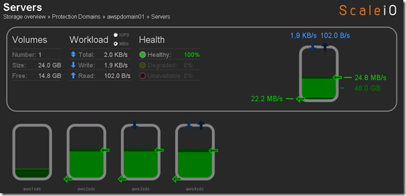
Data is being evacuated from aws1sds:Image(40)
aws1sds removed:Image(41)

Still the same issue:

scaleiovm02:/opt/scaleio/siinstall # scli –mdm_ip 10.10.0.25 –add_sds –sds_ip 54.88.14.30 –protection_domain_name awspdomain01 –device_name /dev/xvdf –storage_pool_name pool03 –sds_name aws5sds
Error: MDM failed command.  Status: SDS already attached to this MDM

I think this is because the aws1sds was already added to the Protection Domain when I created the AMI image.  Now that I removed it from the Protection Domain I am going to terminate the aws5sds instance and create a new AMI image from the aws1sds.

Added aws1sds back to awspdomain01:

scaleiovm02:/opt/scaleio/siinstall # scli –mdm_ip 10.10.0.25 –add_sds –sds_ip 54.86.164.18 –protection_domain_name awspdomain01 –device_name /dev/xvdf –storage_pool_name pool03 –sds_name aws1sds
Successfully created SDS aws1sds. Object ID d99a7c5e0000000d
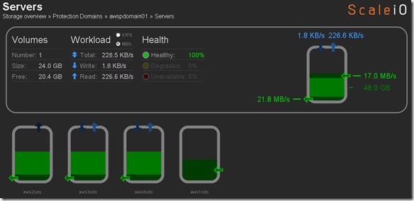
Image(42)

Reprovisioning aws5sds from the new AMI image I created

Add SDS (ScaleIO_AWS5) to Protection Domain and Pool:

scaleiovm02:/opt/scaleio/siinstall # scli –mdm_ip 10.10.0.25 –add_sds –sds_ip 54.88.103.188 –protection_domain_name awspdomain01 –device_name /dev/xvdf –storage_pool_name pool03 –sds_name aws5sds
Successfully created SDS aws5sds. Object ID d99a7c5f0000000e

Success:Image(43)
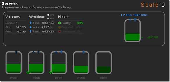
A little cleanup prior to mass deployment

Wanted to change a few things and create a new AMI image to use for deployment so removed aws1sds and aws5sds from awspdomain01:

  • scli –mdm_ip 10.10.0.25 –remove_sds –sds_name aws5sds
  • scli –mdm_ip 10.10.0.25 –remove_sds –sds_name aws1sds

Add aws1sds back to awspdomain01

scaleiovm02:/opt/scaleio/siinstall # scli –mdm_ip 10.10.0.25 –add_sds –sds_ip 54.86.164.18 –protection_domain_name awspdomain01 –device_name /dev/xvdf –storage_pool_name pool03 –sds_name aws1sds
Successfully created SDS aws1sds. Object ID d99a7c600000000f

Deploy 100 SDS nodes in AWS using the AMI image that I created from aws1sds

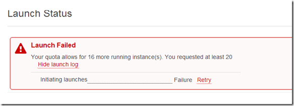
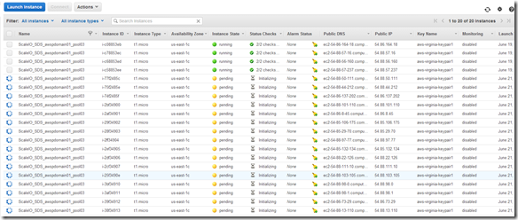
Apparently I have an instance limit of 20 instances.
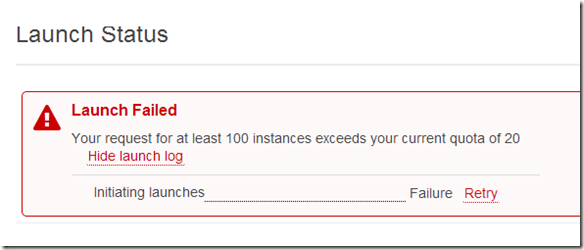
Image(44)

Image(45)

Opened  a ticket with AWS to have my instance limit raised to 250 instances.

Heard back from AWS and here is what they had to say:Image(46)
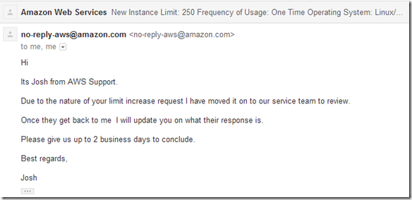
Hopefully next week they will increase my limit to 250 and I can play some more.

So my original plan assuming i didn’t hit the 20 instance limit was to create a new Protection Domain and a new Pool and add my 100+ SDS nodes to the new Protection Domain and Pool like below:

  • New AWS Protection Domain:  scli –mdm_ip 10.10.0.25 –add_protection_domain –protection_domain_name awspdomain02
  • New Storage Pool to AWS Protection Domain:  scli –mdm_ip 10.10.0.25 –add_storage_pool –protection_domain_name awspdomain02 –storage_pool_name pool04

Because I can only add an additional 16 instances (at the current time and I am impatient) I am just going to add the 16 new instances to my existing awspdomain01 and pool03.

Step 1:  Deploy the additional 16 instances using my ScaleIO_SDS AMI image

Note:  I retagged my existing for nodes “ScaleIO_SDS_awspdomain01_pool03”  I will use this tag on the 16 new nodes I am deploying, will make it easy to filter in the AWS console.  Will be important when I grab the details to add the SDS nodes to the awspdomain01 and pool03.

Image(47)

Image(48)


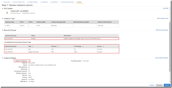
Change the number of instances to be deployed (16 in this case):Image(49)
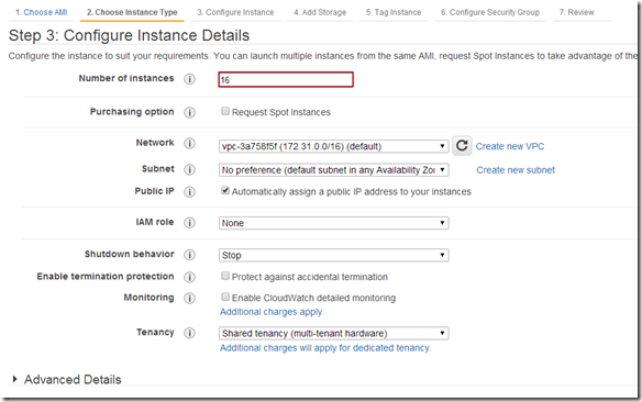
Tag Instances:Image(50)

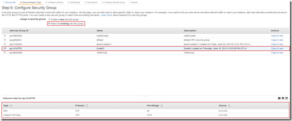
Configure Security Group:Image(51)

Review Instance Details and Launch:Image(52)

Image(53)

Step 2:  Prep to add newly deployed SDS nodes to awspdomian01 and pool03

I used a pretty simple approach for this:

Highlight the nodes in the AWS console and cut-and-paste to Excel (Note:  I filter my list by the tag we applied in the previous step):Image(54)
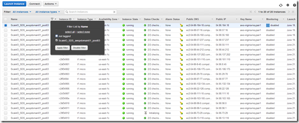
Tip:  I like to highlight from the bottom right of the list to the top left (little easier to control). Cut-and-Past to Excel (or any spreadsheet).Image(55)
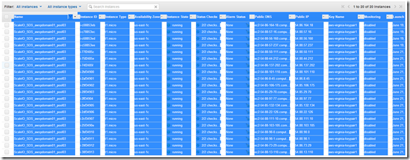
Past (ctrl-v) to Excel without formatting and then do a little cleanup:Image(56)
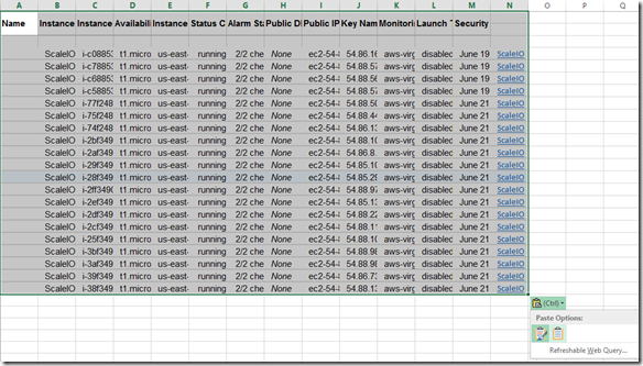
You should end up with a sheet that looks like this:Image(57)

Step 2:  Create the commands in Excel to add the new SDS AWS instances to ScaleIO awspdomain01 and pool03

Note:  I am going to hide columns we don’t need to make the sheet easier to work with.

The only columns we really need are column I (Public IP) and Column L (Launch Time) but I am going to keep column A (Name/Tag ) as well because in a larger deployment scenario you may want to filter on the Name Tag.

I am also going add some new columns:

Column N (Device Name):  This is the device inside the SDS instance that will be used by ScaleIO

Column O,P & Q (node uid, node type and sds_name):  Probably don’t need all of these but I like the ability to filter by node type, sds_name is a concat of nod uid and node type.

Column R (Protection Domain):  This is the Protection Domain that we plan to place the SDS node in

Column S (Pool):  This is the Pool we want the SDS storage to be placed in

You will also notice that “mdm_ip” is in A1 and the mdm ip address is in A2 (A2 is also labeled mdm_ip)
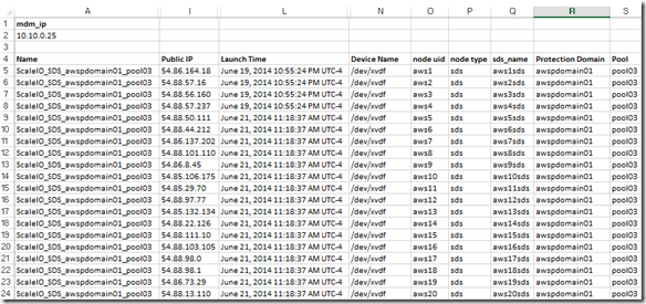
Image(58)

Next I am going to create the commands to add the SDS nodes to our existing awspdomain01 Protection Domain and pool03.

I placed the following formula in Column T:

=”scli –mdm_ip “&mdm_ip&” –add_sds –sds_ip “&I5&” –protection_domain_name “&R5&” –device_name “&N5&” –storage_pool_name “&S5&” –sds_name “&Q5

Image(59)

Now the sheet looks like this:Image(60)

Next I want to filter out the SDS nodes that are already added (aws1sds through aws4sds)

Knowing that I created and added the existing nodes prior to today I just filtered by Launch Time:Image(61)

This leaves me with the list of SDS nodes that will be added to awspdomain01 and pool03:Image(62)

Step 3:  Copy-and-Past the command in Column T (sds_add) to your text editor of choice:Image(63)

Note:  I always do this just to make sure that the commands look correct and that cut-and-paste into my ssh session will be plain text.

Step 4:  Cut-and-Paste the commands into an ssh session on the appropriate ScaleIO node (a node with scli on it, the MDM works)

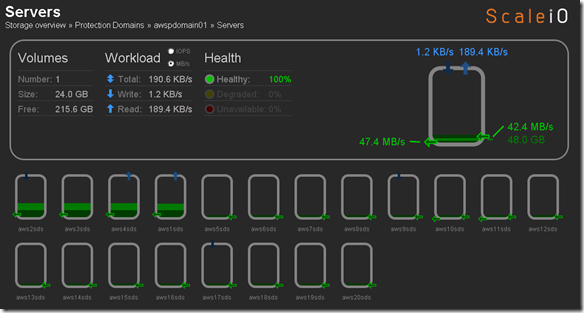
Before we perform Step 4 let’s take a look at what awspdomain01 and pool03 looks like:Image(64)
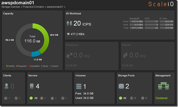
Image(65)

OK, now let’s execute our commands to add the new nodes:Image(66)
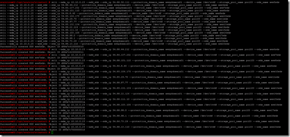
SDS nodes all successfully added and data is being redistributed:Image(67)
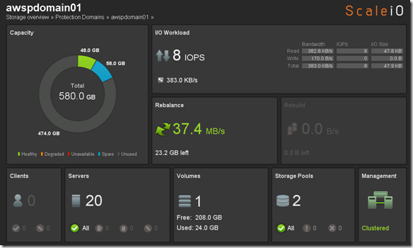
Image(68)

That was pretty easy and pretty cool.  So I am going to take a quick look what I have spent in AWS so far to do everything I posted in my ScaleIO – Chapter II and and ScaleIO – Chapter III posts.  Going to kickoff some benchmarks and will revisit the cost increase.

Image(69)

$1.82 ,the moral of the story it it’s to cheap to stay stupid 🙂  The world is changing, get on board!

Any yes the title of this post may be an homage to Lil Jon and the complex simplicity of “Turn Down for What”

Below you can see the R/W concurrency across the nodes as the benchmark runs.Image
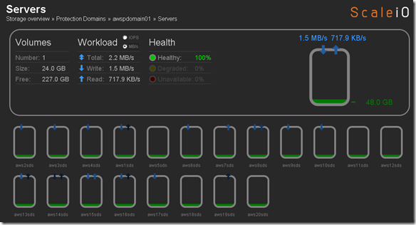
IOzone Preliminary Benchmark Results (20 nodes):

  • Baseline = ScaleIO HDD (Local)
  • Set1 = ScaleIO HDD (20 SDS nodes in AWS)

summary

Preliminary ScaleIO Local HDD vs ScaleIO AWS (20 node) HDD distributed volume performance testing analysis output:  http://nycstorm.com/nycfiles/repository/rbocchinfuso/ScaleIO_Demo/aws_scaleio_20_node_becnchmark/index.html

6/21/2014 AWS Instance Limit Update:  250 Instance Limit Increase Approved.  Cool!

image

6/22/2014 Update:  After running some IOzone benchmarks last night it looks like I used about $7 in bandwidth running the tests.

imageimage

6/25/2014 Update:  Burn it down before I build it up.

AWS cost over the 4-5 days I had the 20 nodes deployed, so I decided to tear it down before I do the 200 node ScaleIO AWS deployment.

imageimage

image

From a cleanup perspective I removed 17 of the 20 SDS nodes, trying to figure out how to remove the last 3 SDS nodes, the Pool and the Protection Domain.  Haven’t worked on this much but once I get it done I plan to start work on the 200 node ScaleIO deployment and testing.
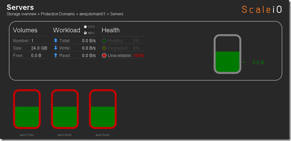
image

ScaleIO – Chapter II: Dreadnought class

Khan: “Dreadnought class. Two times the size, three times the speed. Advanced weaponry. Modified for a minimal crew. Unlike most Federation vessels, it’s built solely for combat.”

Extending ScaleIO to the public cloud using AWS RHEL 6.5 t1.micro instances and EBS and federating with my private cloud ScaleIO implementation.

This post is about federating ScaleIO across the public and private cloud not the “Federation” of EMC, VMware, Pivotal and RSASmile Sorry but who doesn’t love the “Federation”, if for nothing else it takes me back to my childhood.

My Childhood:

Federation President, 2286

If you don’t know what the above means and  the guy on the right looks a little familiar, maybe from a Priceline commercial don’t worry about it,  I just means your part of a different generation (The Next Generation Smile).  If you are totally clueless about the above you should probably stop reading now, if you can identify with anything above it is probably safe to continue.

My Adulthood:

Wow, the above pictorial actually a scares me a little, I really haven’t come very far Smile

Anyway let’s get started exploring the next frontier, certainly not the final frontier.

Note:  I already deployed the four (4) RHEL 6.5 t1.micro AWS instances that I will be using in this post.  This post focuses on the configuration of the instances not the deployment of the AWS instances.  In Chapter III of this series I deploy at a larger scale using a AMI image that I generated from ScaleIO_AWS1 which you will see hos to configure in this posts.

Login to AWS RHEL instance via SSH (Note:  You will have to setup the required AWS keypairs, etc…)Image(24)

Note:  This link provides details on how to SSH to your AWS Linux instances using a key pair(s):  http://docs.aws.amazon.com/AWSEC2/latest/UserGuide/AccessingInstancesLinux.html

Note:  I am adding AWS SDS nodes (ScaleIO Data Server NOT Software Defined Storage) to an existing private cloud ScaleIO implementation so this will only cover installing the SDS component and the required steps to add the SDS nodes to the exiting ScaleIO deployment.

ScaleIO Data Server (SDS) – Manages the capacity of a single server and acts as a backend for data access. The SDS is installed on all servers that contribute storage devices to the ScaleIO system. These devices are accessed through the SDS.

Below is a what the current private cloud ScaleIO deployment looks like:Image(13)

The goal here is to create pool03 which will be a tier of storage that will reside in AWS.

Once logged into your AWS RHEL instance validate that the following packages are installed:  numactl and libaio

    • #sudo –s
    • #yum install libaio
    • #yum install numactl

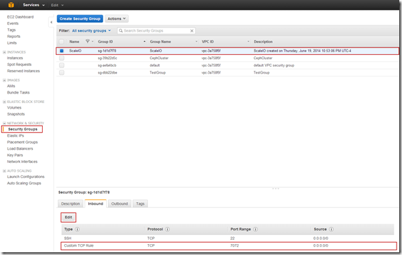
For SDS nodes port 7072 needs to opened.  Because I have a the ScaleIO security group I can make the change in the Security Group.

Note:  This is an environment that is only for testing, there is nothing here that I care about, the data, VMs, etc… are all disposable this opening port 7072 to the public IP is of no concern to me.  In an actual implementation there would likely be a VPN between the public and private infrastructure components and there would not be a need to open port 7072 on the public IP address.

Image(25)

AWS SDS node reference CSV:

IP,Password,Operating System,Is MDM/TB,MDM NIC,Is SDS,is SDC,SDS Name,Domain,SDS Device List,SDS Pool List
#.#.#.#,********,linux,No,,Yes,No,aws1sds,awspdomain1,/dev/xvdf,pool03
#.#.#.#,********,linux,No,,Yes,No,aws2sds,awspdomain1,/dev/xvdf,pool03
#.#.#.#,********,linux,No,,Yes,No,aws3sds,awspdomain1,/dev/xvdf,pool03
#.#.#.#,********,linux,No,,Yes,No,aws4sds,awspdomain1,/dev/xvdf,pool03

Copy the SDS rpm from the AWS1 node to the other 3 nodes:

  • scp /opt/scaleio/siinstall/ECS/packages/ecs-sds-1.21-0.20.el6.x86_64.rpm root@#.#.#.#:~
  • scp /opt/scaleio/siinstall/ECS/packages/ecs-sds-1.21-0.20.el6.x86_64.rpm root@#.#.#.#:~
  • scp /opt/scaleio/siinstall/ECS/packages/ecs-sds-1.21-0.20.el6.x86_64.rpm root@#.#.#.#:~

Note: I copied the ECS (ScaleIO) install files from my desktop to to AWS1 so that is why the rpm is only being copied to AWS2,3 & 4 above.

Add AWS Protection Domain:

  • scli –mdm_ip 10.10.0.25 –add_protection_domain –protection_domain_name awspdomain01

Protection Domain – A Protection Domain is a subset of SDSs. Each SDS belongs to one (and only one) Protection Domain. Thus, by definition, each Protection Domain is a unique set of SDSs.

Add Storage Pool to AWS Protection Domain:

  • scli –mdm_ip 10.10.0.25 –add_storage_pool –protection_domain_name awspdomain01 –storage_pool_name pool03

Storage Pool – A Storage Pool is a subset of physical storage devices in a Protection Domain. Each storage device belongs to one (and only one) Storage Pool. A volume is distributed over all devices residing in the same Storage Pool.  This allows more than one failure in the system without losing data. Since a Storage Pool can withstand the loss of one of its members, having two failures in two different Storage Pools will not cause data loss.

Add SDS to Protection Domain and Pool:

  • scli –mdm_ip 10.10.0.25 –add_sds –sds_ip 54.86.164.18 –protection_domain_name awspdomain01 –device_name /dev/xvdf –storage_pool_name pool03 –sds_name aws1sds
  • scli –mdm_ip 10.10.0.25 –add_sds –sds_ip 54.88.57.16 –protection_domain_name awspdomain01 –device_name /dev/xvdf –storage_pool_name pool03 –sds_name aws2sds
  • scli –mdm_ip 10.10.0.25 –add_sds –sds_ip 54.88.56.160 –protection_domain_name awspdomain01 –device_name /dev/xvdf –storage_pool_name pool03 –sds_name aws3sds
  • scli –mdm_ip 10.10.0.25 –add_sds –sds_ip 54.88.57.237 –protection_domain_name awspdomain01 –device_name /dev/xvdf –storage_pool_name pool03 –sds_name aws4sds

Create 20 GB volume:

  • scli –mdm_ip 10.10.0.25 –add_volume –protection_domain_name awspdomain01 –storage_pool_name pool03 –size 20 –volume_name awsvol01

Some other relevant commands:

  • scli –mdm_ip 10.10.0.25 –remove_sds –sds_name aws1sds
  • scli –mdm_ip 10.10.0.25 –sds –query_all_sds
  • scli –mdm_ip 10.10.0.25 –query_storage_pool –protection_domain_name awspdomain01 –storage_pool_name pool03

Note:  I always use the –mdm_ip switch that way I don’t have to worry where I am running the commands from.

Meta Data Manager (MDM) – Configures and monitors the ScaleIO system. The MDM can be configured in a redundant Cluster Mode with three members on three servers, or in a Single Mode on a single server.

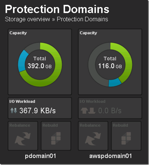
ScaleIO Deployed in AWS and federated with private cloud ScaleIO deploymentImage(26)

My ScaleIO (ECS) implementation now has 3 tiers of storage:

  • Tier 1 (Local SSD) = pdomain01, pool1
  • Tier 2 (Local HDD) = pdomain01, pool2
  • Tier 3 (AWS HDD) = awspdomain01, pool3

Image(27)

Image(28)

Map AWS volume to local SDCs:

  • scli –mdm_ip 10.10.0.25 –map_volume_to_sdc –volume_name awsvol01 –sdc_ip 10.10.0.21
  • scli –mdm_ip 10.10.0.25 –map_volume_to_sdc –volume_name awsvol01 –sdc_ip 10.10.0.22
  • scli –mdm_ip 10.10.0.25 –map_volume_to_sdc –volume_name awsvol01 –sdc_ip 10.10.0.23
  • scli –mdm_ip 10.10.0.25 –map_volume_to_sdc –volume_name awsvol01 –sdc_ip 10.10.0.24

ScaleIO Data Client (SDC) – A lightweight device driver that exposes ScaleIO volumes as block devices to the application residing on the same server on which the SDC is installed.

Map AWS volume to ESX initiators:

  • scli –mdm_ip 10.10.0.25 –map_volume_to_scsi_initiator –volume_name awsvol01 –initiator_name svrsan2011
  • scli –mdm_ip 10.10.0.25 –map_volume_to_scsi_initiator –volume_name awsvol01 –initiator_name svrsan2012
  • scli –mdm_ip 10.10.0.25 –map_volume_to_scsi_initiator –volume_name awsvol01 –initiator_name svrsan2013
  • scli –mdm_ip 10.10.0.25 –map_volume_to_scsi_initiator –volume_name awsvol01 –initiator_name svrsan2014

Note:  I alreadt created the SCSI initiators and named them this is NOT documented in this post.  I plan to craft a A to Z how-to when I get some time.

AWS ScaleIO Datastore now available in VMware (of course there are some steps here, rescan, format, etc…)Image(29)

Figured I would do some I/O just for giggles (I am sure it will be very slow, using t1-micro instance and not at scale):

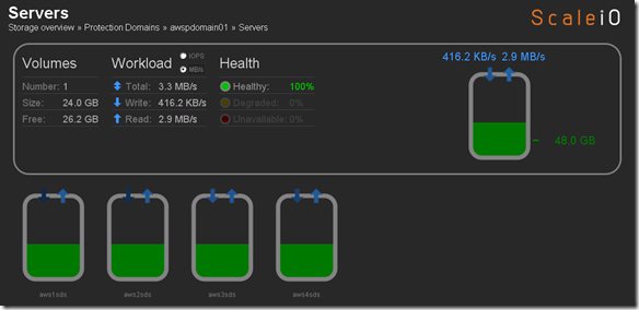
Screenshot below is activity while running I/O load to the AWS volume:Image(31)

Important to note that the public / private ScaleIO federation was PoC just to see how it could / would be done.  It was not intended to be a performance exercise but rather a functional exercise.  Functionally things worked well, the plan is now to scale up the number and type of nodes to see what type of performance I can get from this configuration.  Hopefully no one will push back on my AWS expenses 🙂

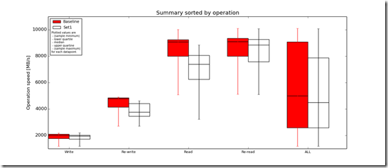
I did some quick testing with FFSB and FIO, after seeing the results returned by both FFSB and FIO i wanted to grab some additional data so I could do a brief analysis so ran IOzone (http://www.iozone.org/) against the AWS ScaleIO volume (awspdomain01, pool03) and the local ScaleIO HDD volume (pdomain01, pool02) for comparison.

 IOzone Results (very preliminary):

  • Baseline = ScaleIO HDD (Local)
  • Set1 = ScaleIO HDD (SDS nodes in AWS)Image(32)

Preliminary ScaleIO Local HDD vs ScaleIO AWS HDD distributed volume performance testing analysis output:  http://nycstorm.com/nycfiles/repository/rbocchinfuso/ScaleIO_Demo/aws_benchmark/index.html

Considering that i only have 4 x t1.micro instances which are very limited in terms of IOPs and bandwidth the above is not that bad.

Next steps:

  • Automate the creation of AWS t1.micro instances and deployment of SDS nodes
  • Additional performance testing
  • Add AWS nodes to Zabbix (http://www.zabbix.com/)

I am interested in seeing what I can do as I scale up the AWS configuration.  Stay tuned.

ScaleIO – Chapter I: Frenemies? The story of a scale-out frenemietecture.

So this post is a slightly modified version of some internal documentation that I shared with my management, the folks at Dell who graciously donated the compute, PCIe SSDs and 10 Gig network for this project and the folks at EMC who of course donated the the ScaleIO licensing (and hopefully soon the ViPR 2.0 licensing).  Due to the genesis of this post and my all around lack of time for editing some of the writing and tense in this post may not always be logical.

Just about everyone knows that Dell and EMC aren’t exactly best friends these days but could there be a better match for this architecture?  Cough, cough, Supermicro, cough, cough Quanta…. but seriously the roll your own Supermicro, Linux, Ceph, Swift, etc… type architecture isn’t for everyone, some people still want reasonably supported hardware and software at pricing that rivals the likes of Supermicro and OSS (Open-source software).  BTW, there is a cost to OSS, it’s called your time.  Think I need to build a private scale-out architecture, I want it to be lower cost, high performance, support both physical and virtual environments and I want the elasticity and the the ability to scale to the public cloud and oh yeah, I want a support mechanism that is enterprise class for both the hardware and software that I deploy as part of this solution.

Most have heard the proverb “the enemy of my enemy  is my friend”, the reality is that Dell and EMC are fenemies whether they know it or not, are willing to admit it or not because I am currently implementing Chapter III in this series and trust me the enemy (competition) is a formidable one, known as the elastic public cloud!  Take your pick, AWS, Google, Azure, ElasticHosts, Bitnami, GoGrid, Rackspcae, etc…  Will they replace the private cloud, probably not (at least not in the foreseeable future) as there are a number of reasons the private cloud needs to exist and will continue to exist, reasons like regulations, economics, control, etc…

In a rapidly changing landscape where the hardware market is infected with the equivalent of the ebola virus, hemorrhaging interest, value and margin.  The sooner we accept this fact and begin to adapt (really adapt) the better our chances of avoiding extinction.  Let’s face it there are many OEMs, VARs, individuals, etc… who are more focused on containment rather than a cure.  All of us who have who have sold, architected, installed, maintained, etc… traditional IT infrastructure face a very real challenge from a very real threat.  The opposing force possess the will and tactics of the Spartans and the might of the Persians, if we (you and I) don’t adapt and think we can continue with business as usual,  more focused on containment than curing our own outdated business models we will face a very real problem in the not so distant future.  Having said the aforementioned there is no doubt that EMC is hyperfocused on software, much of it new (e.g. – ViPR, ScaleIO, Pivotal, etc…) and many tried and true platforms already instantiated in software or planned to be (e.g. – RecoverPoint, Isilon, etc…).  As compute costs continue to plummet more functionality can be supported at the application and OS layers which changes the intelligence needed from vendors.  In the IT plumbing space (specifically storage) the dawn of technologies like MS Exchange DAGs and SQL AlwaysOn Availability Groups have been a significant catalyst for the start of a significant shift, the focus has begun to move to features like automation rather than array based replication.

The market is changing fast, we are all scrambling to adapt, figure out how we will add value in the future of tomorrow.  I am no different than anyone else, spending my time and money on AWS.

image

Anyway there is too much to learn and not enough time, I read more than ever on my handheld device (maybe the 5” screen handheld device is a good idea, always thought it was too large).  As I work on Chapter II of this series I found myself at dinner the other night with my kids reading documentation on the Fabric documentation.  Trying to decide is I should use Fabic to do automate my deployment or just good old shell scripts and the AWSCLI, then my mind started wondering to what do I do after Chapter III, maybe there is a Chapter IV and V with different instance types or maybe I should try Google Compute or Azure, so many choices so little time Smile

Update:  Chapter II and Chapter III of this series already completed and I have actually begun working on Chapter IV.

For sure there will be a ScaleIO and ViPR chapter but I need to wait for ViPR 2.0

This exercise is just my humble effort to become competent in the technologies that will drive the future of enterprise architecture and hopefully say somewhat relevant.

High-level device component list for the demo configuration build:

  • Server Hardware (Qty 4):
    • Dell PowerEdge R620, Intel Xeon E5-2630v2 2.6GHz Processors, 64 GB of RAM
    • PERC H710P Integrated RAID Controller
    • 2 x  250GB 7.2K RPM SATA 3Gbps 2.5in Hot-plug Hard Drive
    • 175GB Dell PowerEdge Express Flash PCIeSSD Hot-plug
  • Networking Hardware:
    • Dell Force10 S4810 (10 GigE Producution Server SAN Switch)
    • TRENDnet TEG-S16DG (1 GigE Management Switch)

High-level software list:

  • VMware ESX 5.5.0 build 1331820
  • VMware vCenter Server 5.5.0.10000 Build 1624811
  • EMC ScaleIO:  ecs-sdc-1.21-0.20, ecs-sds-1.21-0.20, ecs-scsi_target-1.21-0.20, ecs-tb-1.21-0.20, ecs-mdm-1.21-0.20, ecs-callhome-1.21-0.20
  • Zabbix 2.2
  • EMC ViPR Controller 1.1.0.2.16
  • EMC ViPR SRM Suite
  • IOzone 3.424
  • Ubuntu 14.04 LTS 64 bit (Benchmark Testing VM)

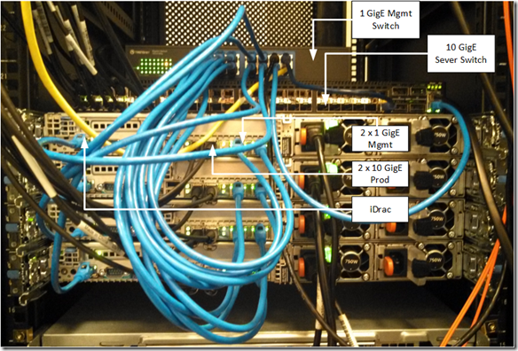
What the configuration physically looks like:Image(7)

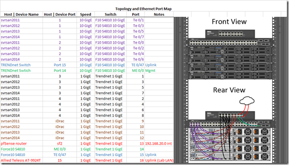
Topology and Layer 1 connections:Image(8)

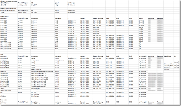
Below are the logical configuration details for the ScaleIO lab environment (less login credentials of course):Image(9)

Dell Force10 S4810 Config: http://nycstorm.com/nycfiles/repository/rbocchinfuso/ScaleIO_Demo/s4810_show_run.txt

Base ScaleIO Config File: http://nycstorm.com/nycfiles/repository/rbocchinfuso/ScaleIO_Demo/scaleio_config_blog.txt

ScaleIO Commands: http://nycstorm.com/nycfiles/repository/rbocchinfuso/ScaleIO_Demo/scalio_install_cmds_blog.txt

ScaleIO environment is up and running and able to be demoed (by someone who knows the config and ScaleIO because most of the configuration is done via CLI and require some familiarity given the level of documentation at this point)

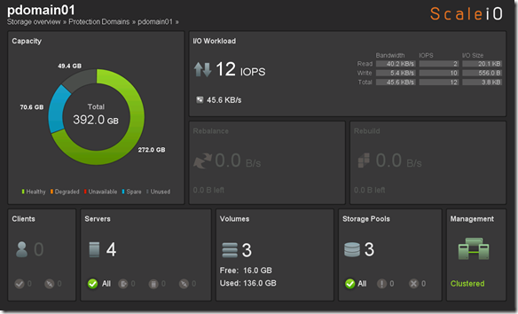
ScaleIO ConsoleImage(10)

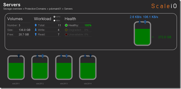
Below you can see that there is 136 GB of available aggregate capacity available across all the ScaleIO nodes (servers).Image(11)

This is not intended to be a ScaleIO internals deep dive but here is some detail on how the ScaleIO usable capacity is calculated:

Total aggregate capacity across SDS nodes:

  • 100/# of SDS servers = % for spare capacity
  • 1/2 half of the remaining capacity for mirroring

For example in a ScaleIO cluster with 4 nodes and 10 GB per node the math would be as follows:

    • 40 GB of aggregate capacity
    • 100/4 = 25% (or 10 GB) for spare capacity
    • .5 * 30 GB (remaining capacity) = 15 GB of available/usable capacity

Configured VMware datastores:Image(12)

  • svrsan201#_SSD – This is the local PCIe SSD on each ESX server (svrsan201#)
  • svrsan201#_local – This is the local HDDs on each ESX server (svrsan201#)
  • ScaleIO_Local_SSD_Datastore01:  The federated ScaleIO SSD volume presented from all four ESX servers (svrsan2011 – 2014)
  • ScaleIO_Local_HDD_Datastore01:  The federated ScaleIO HDD volume presented from all four ESX servers (svrsan2011 – 2014)

Detailed VMware Configuration Output: http://nycstorm.com/nycfiles/repository/rbocchinfuso/ScaleIO_Demo/ScaleIO_VMware_Env_Details_blog.html

To correlate the above back to the ScaleIO backend configuration the mapping looks like this:

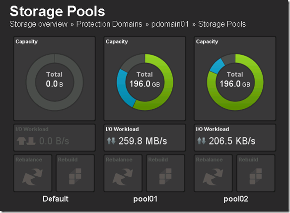
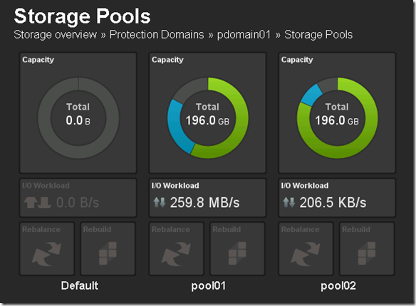
Two (2) configured Storage Pools both in the same Protection Domain

  • pool01 is an aggregate of SSD storage from each ScaleIO node (ScaleIO_VM1, ScaleIO_VM2, ScaleIO_VM3 and ScaleIO_VM4)
  • pool02 is an aggregate of HDD storage from each ScaleIO node (ScaleIO_VM1, ScaleIO_VM2, ScaleIO_VM3 and ScaleIO_VM4)

Note:  Each of the ScaleIO nodes (ScaleIO_VM1, ScaleIO_VM2, ScaleIO_VM3 and ScaleIO_VM4) is tied to a ESX node (ScaleIO_VM1 -> svrsan2011, ScaleIO_VM2 -> svrsan2012, ScaleIO_VM3 -> svrsan2013, ScaleIO_VM4 -> svrsan2014)

Image(13)

Each Storage Pool has configured volumes:

  • pool01 had one (1) configured volume of ~ 56 GB. This volume is presented to the ESX servers (svrsan2011, svrsan2012, svrsan2013 & svrsan2014) as ScaleIO_Local_SSD_Datastore01
  • pool02 had two (2) configured volumes totaling ~ 80 GB.  ScaleIO_Local_HDD_Datastore01 = ~ 60 GB and ScaleIO_Local_HDD_Datastore01 = ~ 16 GB, these to logical volumes share the same physical HDD across the ScaleIO node.

Some Additional ScaleIO implementation Tweaks

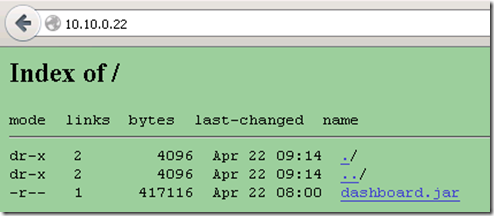
The ScaleIO GUI console seen above is a jar file that needs to be SCPed from the MDM host to your local machine to be run (it lives in /opt/scaleio/ecs/mdm/bin/dashboard.jar).  I found this to be a bit arcane so installed thhtp (http://www.acme.com/software/thttpd/) on the MDM server to make it easy to get the dashboard.jar file.

On the MDM server do the following:

  1. zypper install thttpd
  2. cd /srv/www/htdocs
  3. mkdir scaleio
  4. cd ./scaleio
  5. cp /opt/scaleio/ecs/mdm/bin/dashboard.jar .
  6. vi /etc/thttpd.conf
  7. change www root dir to “/srv/www/htdocs/scaleio”
  8. restart the thttpd server “/etc/init.d/thttpd restart”
  9. Now the .jar file can be downloaded using http:\\10.10.0.22\

Image(14)

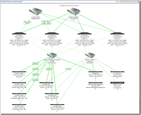
Wanted a way to monitor the health and performance (cpu, mem, link utilization, etc…) of the ScaleIO environment.  Including ESX servers, ScaleIO nodes, benchmark test machines, switches, links, etc…

  1. Deployed Zabbix (http://www.zabbix.com/) to monitor the ScaleIO environment
  2. Built demo environment topology with active elementsImage(15)
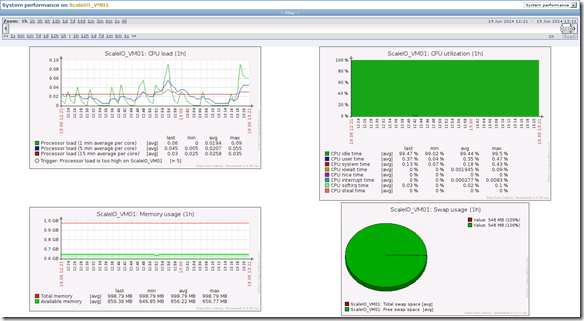
  3. Health and performance of all ScaleIO nodes, ESX nodes, VMs and infrastructure components (e.g. – switches) can be centrally monitoredImage(16)

Preliminary Performance Testing

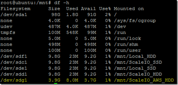
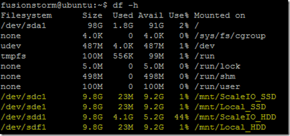
Testing performed using a single Linux VM with the following devices mounted:Image(17)

Image(18)

Performance testing was done using IOzone (http://www.iozone.org/) and the results were parsed, aggregated and analyzed using python (http://www.python.org/), R (http://www.r-project.org/), SciPy (http://www.scipy.org/) and Jinja2 (http://jinja.pocoo.org/)

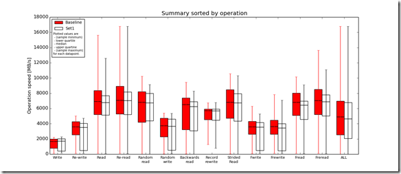
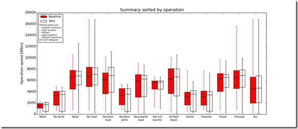
Due to limited time and the desire to capture some quick statistics a single run was made against each device using IOzone using the local HDD and SSD devices for the baseline sample data and the ScaleIO volumes as the comparative data set.

Test 1:  Local HDD device vs ScaleIO HDD distributed volume (test performed against /mnt/Local_HDD and /mnt/ScaleIO_HDD, see table above)

Test 2:  Local SSD device vs ScaleIO SSD distributed volume (test performed against /mnt/Local_SSD and /mnt/ScaleIO_SSD, see table above)

Note:  Local (HDD | SSD) = a single device in in a single ESX server, ScaleIO (HDD | SSD) makes used the same HDD and SSD device in the server used in the local test but also all other HDD | SSD devices in other nodes, to provide aggregate capacity, performance and protection.

ViPR Installed and Configured

  • ViPR is deployed but version 1.1.0.2.16 does not support ScaleIO.
  • Note:  ScaleIO support will be added in ViPR version 2.0 which is scheduled for release in Q2.Image(21)Image(22)

EMC ViPR SRM deployed but haven’t really done anything with it to date.Image(23)

ScaleIO SDS nodes in AWS

  1. Four (4) AWS RHEL t1.micro instances provisioned and ScaleIO SDS nodes deployed and configured.Image(24)
  2. Working with EMC Advanced Software Division to get an unlimited perpetual ScaleIO license so I can add the AWS SDS nodes to the existing ScaleIO configuration as a new pool (pool03).
  3. Do some testing against the AWS SDS nodes.  Scale number of nodes in AWS to see what type or performance I can drive in with t1. micro instances.

Todo list (in no particular order)

  1. Complete AWS ScaleIO build out and federation with private ScaleIO implementation
    1. Performance of private cloud compute doing I/O to AWS ScaleIO pool
    2. Using ScaleIO to migrate between the public and private cloud
    3. Linear scale in the public and private cloud leveraging ScaleIO
  2. Complete ViPR SRM configuration
  3. Comparative benchmarking and implementation comparisons
    1. ScaleIO EFD pool vs ScaleIO disk pool
    2. ScaleIO EFD vs SAN EFD
    3. ScaleIO vs VMware VSAN
    4. ScaleIO vs Ceph, GlusterFS, FhGFS/BeeGFS whatever other clustered file system I can make time to play with.
    5. ScaleIO & ViPR vs Ceph & Swift (ViPR 2.0 Required)
  4. Detailed implementation documentation
    1. Install and configure
    2. Management

Progress on all of the above was slower than I had hoped, squeezing in as much as possible in late night and on weekends because 120% of my time is consumed on revenue producing activity.

Quickly Gather RecoverPoint Replication Stats

It’s been a while since I posted, I think I got to caught up in writing lengthy posts (which I often never completed) rather than just publishing content as I have it and as my personal time allows.  This post is the start of a new philosophy.

Last week I had a need to quickly grab some replication stats from RecoverPoint and I thought I would share the process and code I used to do this.

Prerequisites:  plink, sed, awk, head, tail and egrep

Note:  Because this is not a tutorial I am not going to talk about how to get the requirements configured on your platform.  With that said you should have no issues getting the prerequisites work on Windows or Linux (for Windows Cygwin may be a good option).

https://gist.github.com/rbocchinfuso/9369708

The resulting output is a CSV which can be opened in Excel (or whatever) to produce a table similar to the following:

image

My Iomega ix2 and my new 3 TB USB drive

Purchased 3 TB Seagate USB 3.0 drive from Amazon (http://amzn.to/TpduBU)

Waited… Very excited to connect to my ix2….

A few days later my 3 TB USB expansion drive arrived.  I hurried to unpack and connect to my ix2 expecting plug-and-play.  I plugged by no play.

clip_image001

An overwhelming feeling of sadness consumed me, followed by WTF then the joy of knowing I could and would hack this to make it work.

Knowing that this Iomega thing had to be running Linux I began to scour web for how to enable SSH with Firmware Version 3.3.2.29823

Found plenty of how to information on Firmware Version 2.x but 3.x (Cloud Enabled Firmware) is a bit more sparse.

Finally to enable SSH:  http://ip/diagnostics.html

clip_image002

SSH now enabled, opened PuTTY and SSH to device.

Username:  root
Password:  soho

Boom!  In….

clip_image003

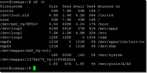
A quick “df -h” shows my currently configured capacity:

clip_image004

A quick “cat /proc/scsi/usb-storage/4” followed by a “fdisk -l” reveals the drive is being seen by the ix2.

clip_image005

clip_image006

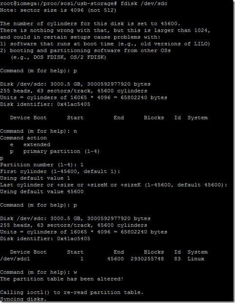
Created partition on /dev/sdc, “fdisk /dev/sdc”

clip_image007

Now what?

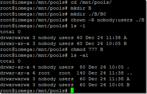
Hmmmmm…. Maybe I can create a mount point on /mnt/pools/B/B0, seems logical.

clip_image008

clip_image009

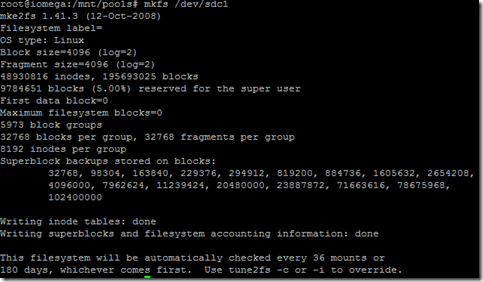
Whoops forgot to mkfs.

Run “mkfs /dev/sdc1”

clip_image010

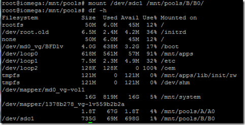
“mount /dev/sdc1 /mnt/pools/B/B0/”

clip_image011

Hmmmm…..

“umount /dev/sdc1”

Tried to partition with parted (core dumps, ix2 running ver 1.8.  pretty sure GPT partition support not ready for primetime in vet 1.8)

Let see if I can get a new version of parted.

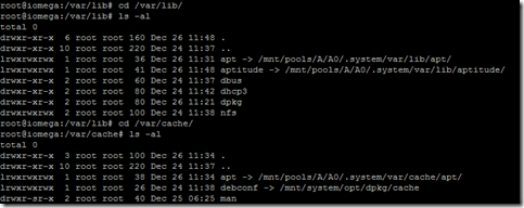
Enabled apt-get (required a little work)

cd /mnt/pools/A/A0
mkdir .system
cd .system

mkdir ./var; mkdir ./var/lib/; mkdir ./var/cache; mkdir ./var/lib/apt; mkdir ./var/cache/apt;  mkdir ./var/lib/apt/lists; mkdir ./var/lib/apt/lists/partial; mkdir ./var/cache/apt/archives;  mkdir ./var/cache/apt/archives/partial; mkdir ./var/lib/aptitude

(I think that is all the required dirs, you will know soon enough)

cd /var/lib
ln -s /mnt/pools/A/A0/.system/var/lib/apt/ apt
ln -s /mnt/pools/A/A0/.system/var/lib/aptitude/ aptitude
cd /var/cache
ln -s /mnt/pools/A/A0/.system/var/cache/apt/ apt

run “apt-get update”

Should run without issue.

run “aptitude update”
Note:  Should run without issue.

clip_image012

Jettison that idea, not enough space on root and /mnt/apps to install new version of parted and required dependencies.

New approach:

run “dd /dev/zero /dev/sdc”

Let run for a minute of so to clear all partition info (ctrl-c) to stop

Download EASEUS Partition Master 9.2.1 from filehippo (http://www.filehippo.com/download_easeus_partition_master_home/)

Install EASEUS Partion Master 9.2.1 on Windows 7 desktop
Connect 3 TB Seagate USB drive to Windows 7 desktop
Partition and format partition ext3 using EASEUS Partion Master 9.2.1
Note:  This takes a little while.

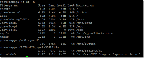
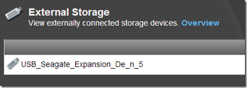
Once complete I connected the drive to my Iomega ix2

Voila!

clip_image013

clip_image014

Cleaned up the “/mnt/pools/B directory” I created earlier (“rm -rf /mnt/pools/B”)

Reboot my ix2 (make sure I didn’t jack anything up) and enjoy my added capacity.

image

Pretty sick footprint for ~ 4.5 TB of storage (1.8 TB of it R1 protected).

DNS and Disaster Recovery

I’ve been conducting DR tests and site failovers for years using a myriad of host based and array based replication technologies.  By now the tasks of failing the host over from site A to site B and gaining access to replicated data is a highly predictable and controllable event.  What I often find is that little issues like time being out-of-sync due to NTP server issue, a host needing to be rejoined to the domain or the dreaded missing or fat fingered DNS entry tend to slow you down.

I recently ran a DR test where in the prior test a DNS entry was fat fingered, the bad DNS entry impacted the failback and extended the test time by about 5 hours.  Prior to this year’s test I decided to safeguard the DNS component of the test.  I crafted a small shell script to record and check the DNS entries (forward and reverse),  The plan would be as follows:

  1. Capture DNS entries prior to the DR test and save as the production gold copy (known working production DNS records)
  2. Capture DNS entries following the failover to the DR location and DNS updates.  Ensure that the DNS entries match the documented DR site IP schema.
  3. Finally capture the DNS entries post failback to the production site.  Diff the pre-failover production site DNS entries (gold copy) with the post-failback production site DNS entries.

The fail-safe DNS checks proved to be very valuable, uncovering a few issues on failover and failback.  Below is my script, I ran the shell script from a Linux host, if you need to run on Windows and don’t want to rewrite you could try Cygwin (I don’t believe the “host” command is natively packaged with Cygwin but it could probably be compiled, haven’t looked around much)  or you could download VirtualBox and run a Linux VM. Hopefully you find this useful.

#!/bin/bash
#script to check dns registrations

if [ $# -lt 1 ]
then
  echo "Usage : $0 [prod|dr]"
  exit
fi

LOGFILE="checkdns_$1.log.`date +"%m%d%y-%H%M%S"`"
cp /dev/null $LOGFILE    # creates an empty $LOGFILE

echo "...Starting DNS record check"

while read DNSRECORD RECORDTYPES ; do
  for RECORDTYPE in $RECORDTYPES ; do
    echo "...Checking DNS [$RECORDTYPE] record for $DNSRECORD"
    host -t $RECORDTYPE $DNSRECORD | sort >>$LOGFILE
    sleep 1
  done
done < "hosts_$1.in"

echo "...Done"
echo "...Results logged to $LOGFILE"

Note:  you will need two input files:  “hosts_prod.in” and “hosts_dr.in”. These input files should contain your lookups for each site.

.in file example (syntax for .in files is “hostname | IP [space] record type”):
host1 a
host2 a
192.168.100.1 a
192.168.100.2 a

Syntax to execute the script is as follows “./checkdns.sh [prod | dr]”

Mapping RDM Devices

This post was driven by a requirement to map RDM volumes on target side in preparation for a disaster recovery test.  I thought I would share some of my automation and process with regards to mapping RDM devices that will be used to present RecoverPoint replicated devices to VMs as part of a DR test.

Step 1:  Install VMware vCLI and PowerCLI
Step 2:  Open PowerCLI command prompt
Step 3:  Execute addvcli.ps1 (. .\addvcli.ps1)
function Add-vCLIfunction {
  <#
  .SYNOPSIS
    Adds the VMware vSphere Command-Line Interface perl scripts as PowerCLI functions.

  .DESCRIPTION
    Adds all the VMware vSphere Command-Line Interface perl scripts as PowerCLI functions.
    VMware vSphere Command-Line Interface has to be installed on the system where you run this function.
    You can download the VMware vSphere Command-Line Interface from:
    http://communities.vmware.com/community/vmtn/server/vsphere/automationtools/vsphere_cli?view=overview

  .EXAMPLE
    Add-vCLIfunction
    Adds all the VMware vSphere Command-Line Interface perl scripts as PowerCLI functions to your PowerCLI session.

  .COMPONENT
    VMware vSphere PowerCLI

  .NOTES
    Author:  Robert van den Nieuwendijk
    Date:    21-07-2011
    Version: 1.0
  #>

  process {
    # Test if VMware vSphere Command-Line Interface is installed
    If (-not (Test-Path -Path "$env:ProgramFiles\VMware\VMware vSphere CLI\Bin\")) {
      Write-Error "VMware vSphere CLI should be installed before running this function."
    }
    else {
      # Add all the VMware vSphere CLI perl scripts as PowerCLI functions
      Get-ChildItem -Path "$env:ProgramFiles\VMware\VMware vSphere CLI\Bin\*.pl" | ForEach-Object {
        $Function = "function global:$($_.Name.Split('.')[0]) { perl '$env:ProgramFiles\VMware\VMware vSphere CLI\bin\$($_.Name)'"
        $Function += ' $args }'
        Invoke-Expression $Function
      }
    }
  }
}
Step 4:  Execute getluns.ps1 (. .\getluns.ps1)
#Initialize variables
#Replace [INSERT VCENTER SERVER NAME] with your vCenter server name, leave preceding and and trailing "
$VCServer = "[INSERT VCENTER SERVER NAME]"
$objLuns = @()
$objRDMs = @()

#Connect to vCenter Server
Connect-VIServer $VCServer

$clusters = Get-cluster

foreach ($cl in $clusters) {
    $clv = $cl | Get-View
    if ($clv.Host.count -gt 0) {
        #assume that all ESX hosts see the same luns
        $vmhost = get-view $clv.host[0]
        #Get ScsiLuns except local storage
        $ScsiLuns = $vmhost.Config.StorageDevice.ScsiLun  | ? {$_.canonicalname -notmatch "vmhba0"}
        #Get Datastore volumes
        $Datastores = $vmhost.Config.FileSystemVolume.MountInfo
        foreach ($Lun in $ScsiLuns) {
            #Define Custom object
            $objVolume = "" | Select ClusterName,LunName,LunUuid,Lunsize,VolumeName

            #Add porperties to the newly created object
            $objVolume.ClusterName = $clv.Name
            $objVolume.LunName = $Lun.CanonicalName
            $objVolume.LunUuid = $Lun.Uuid
            $objVolume.LunSize = $Lun.Capacity.Block * $Lun.Capacity.BlockSize / 1GB

            foreach ($vol in $Datastores | % {$_.volume}) {
                if ($vol.extent | % {$_.diskname -eq $Lun.CanonicalName}) {
                    $objVolume.VolumeName = $vol.Name
                }
            }
            $objLuns += $objVolume

        }
    }
    #RDM information
    $vms = $cl | Get-VM  | Get-View
    if ($null -ne $vms) {
        foreach($vm in $vms){
            foreach($dev in $vm.Config.Hardware.Device){
                if(($dev.gettype()).Name -eq "VirtualDisk"){
                    if(($dev.Backing.CompatibilityMode -eq "physicalMode") -or
                        ($dev.Backing.CompatibilityMode -eq "virtualMode")){
                        $rdm = "" | select VMName, LunUuid, DiskLabel
                        $rdm.VMName = $vm.Name
                        $rdm.LunUuid = $dev.Backing.LunUuid
                        $rdm.DiskLabel = $dev.DeviceInfo.Label
                        $objRDMs += $rdm
                    }
                }
            }
        }
    }
}

foreach ($rdm in $objRDMs) {
    foreach ($disk in $objLuns) {
         if ($disk.LunUuid -eq $rdm.LunUuid) {$disk.VolumeName = $rdm.VMName + "/" + $rdm.DiskLabel}
     }
}

$objLuns | export-csv "scsiluns.csv" -notypeinformation -useculture

Disconnect-VIServer -Confirm:$false
Step 5:  Execute mpath.ps1 (. .\mpath.ps1)
Add-vCLIfunction
$env:VI_USERNAME="root" 
$env:VI_PASSWORD="password"

 $result = foreach($esx in Get-VMHost){
  esxcfg-mpath -l --server $esx.Name | %{
        if($_.Length -gt 0){
            if($_.Contains(': ')){
                $temp = $_.Split(":")
				$desc = $temp[0].trim(0)
				$value = $temp[1..50] -join ":"
				Add-Member -InputObject $obj -Name $desc.trim() -Value $value.trim() -MemberType NoteProperty
            }
            else{
                $obj = New-Object PSObject -Property @{
                    VMHost = $esx.Name
                    Name = $_
                }
            }
        }
        else{
            $obj
        }
    }
    $obj
}

$result | export-csv "mpath.csv" -notypeinformation -useculture
Step 6:  Get SP collect from EMC CLARiiON / VNX array
At this point you should have all the data required to map the RDM volumes on the DR side.  I simply import the two CSVs generated by the scripts into excel (scsiluns.csv, mpath.csv) as well as the LUNs tab from the SP Collect (cap report).
Using Excel and some simple vlookups with the data gathered above you can create a table that looks like the following:
I could probably combine these three scripts into one but under a time crunch so just needed the data, maybe I will work on that at a later date or maybe someone can do it and share with me.

Repurposing old EMC Centera nodes

This is the first in a multi-part series on repurposing old EMC equipment.  I recently acquired six  EMC Centera nodes, two of the nodes with 4x1TB SATA drives and four of the nodes with 4x500GB SATA drives so I started thinking what can I do with these Pentium based machines with 1 GB of RAM and a boat load of storage.  An idea hit me to create a NAS share leveraging a global file system to aggregate the capacity and performance across all the Centera nodes.  Seemingly simple there was a challenge here, most modern day global file systems like GlusterFS or GFS2 require a 64 bit processor architecture, the Centera nodes use 32 bit Pentium processors.  After spending a vacation day researching I identified two possible Global file systems as potential options, XtreemFS and FraunhoferFS (fhgfs).  I discovered fhgfs first and it looked pretty interesting, a fairly traditional Global File System consisting of metadata nodes and storage nodes (I came across this presentation which provides a good overview of the FraunhoferFS.  While fhgfs provided the basics of what I was looking for the missing link was how I was going to protect the data, fhgfs for the most part relied on hardware RAID for node survivability, because the Centera nodes are built to run EMC’s CentraStar an OS which leverages RAIN (Redundant Array of Independent Nodes) no redundancy is built in at the node level.  EMC acquired Centera and CentraStar from a Belgian company named FilePool in 2002.  As I thought trough some possible workarounds I stumbled across XtreemFS an interesting object based global file system, what was most interesting was the ability to replicate objects for redundancy.  At this point I decided to attempt to move forward with XtreemFS, my single node install went well, no issues  to really speak of as I moved towards the multi node configuration I was beginning to get core dumps when starting the daemons, is was at this point that I decided to give fhgfs a try, thinking that in phase 2 of the project I could layer on either rsync of drbd to protect the data (not there yet so not sure how well this theory will play out).  The fhgfs installed fairly easily and is up and running, the rest of this blog will walk you though the steps that I took to prepare the old Centera nodes, install Ubuntu and configure Ubuntu server, install an configure fhgfs.

Because the Centera nodes came out of a production environment they were wiped prior to leaving the production data center (as a side note DBAN booted form a USB key was used to perform the wipe of each node).  So with no data on the four Centera node internal drives the first step was to install a base OS on each node.  Rather than use a USB CD-ROM (only had one) I decided to build a unattended PXE boot install.

Phase 1:  Basic Environment Prep:

Step 1:  Build PXE Server (because this is not a blog on how to build a PXE server I suggest doing some reading).  The following two links should be very helpful:  https://help.ubuntu.com/community/PXEInstallServer, https://help.ubuntu.com/community/PXEInstallMultiDistro. I built my PXE boot server on Ubuntu 12.04 server but the process in pretty much as documented in the above two links.  You can also Google “ubuntu pxe boot server”.

Note:  One key is to be sure to install Apache and copy your Ubuntu distro to a http accessible path.  This is important when creating your kickstart configuration file (ks.cfg) so you can perform a completely automated install.  My ks.cfg file.

Step 1A:  Enter BIOS on each Centera and reset to factory defaults, make sure that each node has PXE boot enabled on the NICs.

Note:  I noticed on some of the nodes that the hardware NIC enumeration does not match Ubuntu’s ETH interface enumeration (i.e. – On 500GB nodes ETH0 is NIC2) just pay attention to this as it could cause some issues, if you have the ports just cable all the NICs to make life a little easier.

Step 1B:  Boot servers and watch the magic of PXE.  Ten minutes from now all the servers will be booted and at the “kickstart login:” prompt.

Step 2:  Change hostname and install openssh-server on each node.  Login to each node, vi /etc/hostname and update to “nodeX”, also execute apttidude install openssh-server (openssh-server will be installed form the PXE server repo, I only do this no so I can do the rest of the work remotely instead of sitting at the console).

Step 3:  After Step 2 is complete reboot the node.

Step 4:  Update /etc/apt/sources.list

Step 4 Alternative:  I didn’t have the patience to wait for the repo to mirror but you may want to do this and copy you sources.list.orig back to sources.list at a later date.

Note:  If you need to generate a a sources.list file with the appropriate repos check out http://repogen.simplylinux.ch/

Step 4A:  Add the FHGFS repo to the /etc/sources.list file

deb http://www.fhgfs.com/release/fhgfs_2011.04 deb6 non-free

Step 4A:  Once you update the /etc/sources.list file run an apt-get update to update the repo, followed by an apt-get upgrade to upgrade distro to latest revision.

Step 5:  Install lvm2, default-jre, fhgfs-admon packages

aptitude install lvm2
aptitude install default-jre
aptitude install fhgfs-admon

Phase 2:  Preparing Storage on each node:

Because the Centera nodes use JBOD drives I wanted to get the highest performance by striping within the node (horizontally) and across the nodes (vertically).  This section focuses on the configuration of horizontal striping on each node.
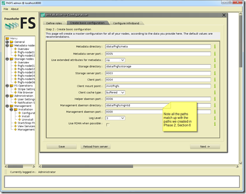
Note:  I probably could have taken a more elegant approach here, like boot for USB key and use the entire capacity of the four internal disks for data but this was a PoC so didn’t get overly focused on this.  Some of the workarounds I use below could have probably been avoided.

  1. Partition the individual node disks
    1. Run fdisk –l (will let you see all disks and partitions)
    2. For devices that do not have partitions create a primary partition on each disk with fdisk (in my case /dev/sda1 contained my node OS, /dev/sda6 was free, /dev/sdb, /dev/sdc and /dev/sdd had no partition table so I created a primary partition dev/sdb1, /dev/sdc1 and /dev/sdd1)
  2. Create LVM Physical Volumes (Note: If you haven’t realized it yet /dev/sda6 will be a little smaller than the other devices, this will be important later.)
      1. pvcreate /dev/sda6
      2. pvcreate /dev/sdb1
      3. pvcreate /dev/sdc1
      4. pvcreate /dev/sdd1
  3. Create a Volume Group that contains the above physical volumes
    1. vgcreate fhgfs_vg /dev/sda6 /dev/sdb1 /dev/sdc1 /dev/sdd1
    2. vgdisplay (make sure the VG was created)
  4. Create Logical Volume
    1. lvcreate -i4 -I4 -l90%FREE -nfhgfs_lvol fhgfs_vg –test
      1. Above command runs a test, notice the –I90% flag, this says to only use 90% of each physical volume.  Because this is a stripe and the available extents differ on /dev/sda6 we need to equalize the extents by consuming on 90% of the available exents.
    2. lvcreate -i4 -I4 -l90%FREE -nfhgfs_lvol fhgfs_vg
      1. Create the logical volume
    3. lvdisplay (verify that the lvol was created)
    4. Note:  The above commands performed on a node with 1TB drives, I also have nodes with 500GB drives in the same fhgfs cluster.  Depending on the the drive size in the nodes you will need to make adjustments so that the extents are equalized across the physical volumes.  As an example on the nodes with the 500GB drives the lvcreate commands looks like this lvcreate -i4 -I4 -l83%FREE -nfhgfs_lvol fhgfs_vg.
  5. Make a file system on the logical volume
    1. lvcreate -i4 -I4 -l83%FREE -nfhgfs_lvol fhgfs_vg
  6. Mount newly created file system and create relevant directories
    1. mkdir /data
    2. mount /dev/fhgfs_vg/fhgfs_lvol /data
    3. mkdir /data/fhgfs
    4. mkdir /data/fhgfs/meta
    5. mkdir /data/fhgfs/storage
    6. mkdir /data/fhgfs/mgmtd
  7. Add file system mount to fstab
    1. echo “/dev/fhgfs_vg/fhgfs_lvol     /data     ext4     errors=remount-ro     0     1” >> /etc/fstab

Note:  This is not a LVM tutorial, for more detail Google “Linux LVM”

Enable password-less ssh login (based on a public/private key pair) on all nodes

  1. On node that will be used for management run ssh-keygen (in my environment this is fhgfs-node01-r5)
    1. Note:  I have a six node fhgfs cluster fhgfs-node01-r5 to fhgfs-node06-r5
  2. Copy the ssh key to all other nodes.  From fhgfs-node01-r5 run the following commands:
    1. cat ~root/.ssh/id_dsa.pub | ssh root@fhgfs-node02-r5 ‘cat >> .ssh/authorized_keys’
    2. cat ~root/.ssh/id_dsa.pub | ssh root@fhgfs-node03-r5 ‘cat >> .ssh/authorized_keys’
    3. cat ~root/.ssh/id_dsa.pub | ssh root@fhgfs-node04-r5 ‘cat >> .ssh/authorized_keys’
    4. cat ~root/.ssh/id_dsa.pub | ssh root@fhgfs-node05-r5 ‘cat >> .ssh/authorized_keys’
    5. cat ~root/.ssh/id_dsa.pub | ssh root@fhgfs-node06-r5 ‘cat >> .ssh/authorized_keys’
  3. Note:  for more info Google “ssh with keys”

Configure FraunhoferFS (how can you not love that name)

  1. Launch the fhgfs-admon-gui
    1. I do this using Cygwin-X on my desktop, sshing to the fhgfs-node01-r5 node, exporting the DISPLAY back to my desktop and then launch the fhgfs-admon-gui.  If you don’t want to install Cygwin-X Xmingis a good alternative.
      1. java -jar /opt/fhgfs/fhgfs-admon-gui/fhgfs-admon-gui.jar
    2. Note:  This is not a detailed fhgfd install guide, reference the install guide for more detail http://www.fhgfs.com/wiki/wikka.php?wakka=InstallationSetupGuide
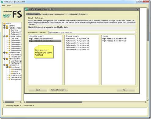
  2. Adding Metadata servers, Storage servers, Clients
    1. SNAGHTML12587da
  3. Create basic configuration
    1. SNAGHTML12f1d17
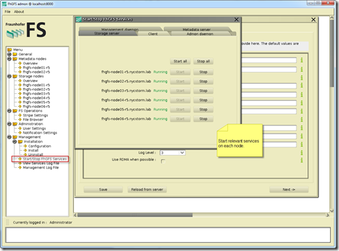
  4. Start Services
    1. SNAGHTML13277e3
  5. There are also a number of CLI command that can be used
    1. image
    2. e.g. – fhgfs-check-servers
      1. image
  6. If all works well a “df –h”yield the following
    1. image
    2. Note the /mnt/fhgfs mount point (pretty cool)

Creating a CIFS/NFS share

  1. Depending on how you did the install of you base Ubuntu system you likely need to load the Samba and NFS packages (Note:  I only loaded these on my node01 and node02 nodes, using these nodes as my CIFS and NFS servers respectively)
    1. aptitude install nfs-server
    2. aptitude install samba
  2. Configure Samba and/or NFS shares from /mnt/fhgfs
    1. There are lot’s or ways to do this, this is not a blog on NFS or Samba so refer to the following two links for more information:
      1. NFS:  https://help.ubuntu.com/community/SettingUpNFSHowTo
      2. Samba/CIFS:  http://www.samba.org/
    2. As a side note I like to load Webmin on the for easy web bases administration of all the nodes, as well as NFS and Samba
      1. wget http://downloads.sourceforge.net/project/webadmin/webmin/1.590/webmin_1.590_all.deb?r=http%3A%2F%2Fwww.webmin.com%2F&ts=1345243049&use_mirror=voxel
      2. Then use dpkg –i webmin_1.590_all.deb to install
      3. image

Side note:  Sometime when installing a debian package using dpkg you will have unsatisfied dependencies.  To solve this problem just follow the following steps:

  1. dpkg –i webmin_1.590_all.deb
  2. apt-get -f –force-yes –yes install

Performance testing, replicating, etc…

Once I finished the install it was time to play a little.  From a windows client I mapped to the the share that I created from the fhgfs-node01-r5 and started running some I/O to the FraunhoferFS….. I stared benchmarking using with IOzone, my goal is to compare and contrast my FraunhoferFS and NAS performance with other NAS products like NAS4Free, OpenFiler, etc… I also plan to do some testing with Unison, rsync and drdb for replication.

This is a long post so I decided to create a separate post for performance and replication.  To wet your appetite here are some the early numbers from the FhGFS NAS testing.

image

image

image

image

Created the above output quickly, In my follow-up performance post I will document the test bed, publish all the test variants and platform comparisons.  Stay tuned…